


This ADC is based on patented Avia technology, and represents an analog front-end device which offers all the required elements for building an accurate load cell application: the internal regulator allows powering up both the ADC section and excitation of the load cell, two 24bit differential channels with the low noise programmable gain amplifier with 32, 64, and 128 gain factor, which allow measurement range selection, mains power 50Hz and 60Hz interference rejection, selectable data output frequency up to 80 samples per second (SPS), and a simple serial communication interface. Load Cell click can be used in a wide range of weight measurement applications, but it can be also utilized to measure the strain force applied on shafts, machine parts, and other similar objects, exposed to forces that cause strain.
How does it work?
The Load Cell click is based on the HX711, a specialized 24bit analog to digital converter (ADC), designed for weight scale applications, made by Avia Semiconductor. Among other sections, this device incorporates two high resolution (24bit) A/D converters (ADC) with differential inputs and internal low-noise programmable gain amplifiers. Since the input voltages are very low, this is required in order to obtain the best possible signal to noise ratio from the load cell connected at the input terminals.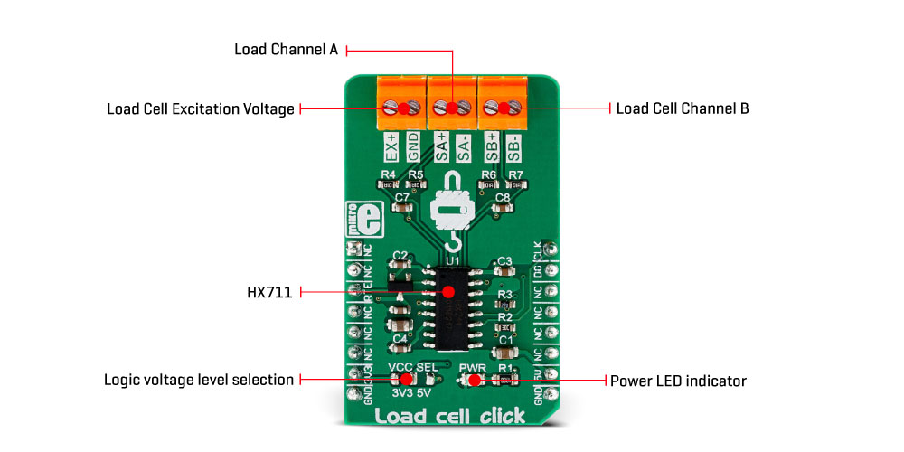
As already mentioned before, the main task of the HX711 IC is to sample the voltage across the bridge as accurately as possible and with the least amount of noise. The Wheatstone bridge formed by strain gauges is attached to an excitation power source, so that the resistance changes can be detected. The HX711 has a dedicated regulated voltage output, which is used to provide the necessary excitation voltage. Two differential inputs are used to connect the loads, offering various gain factors. The first differential input (labeled as A) offers a selectable gain of 64 X or 128 X. The second differential input (labeled as B) offers fixed 32X gain factor. This offers a possibility to select the desired gain factor, according to the used load cell and the magnitude of the strain force.
Load Cell click offers serial communication utilizing the on-chip clock oscillator. The data output rate is selectable and depends on the logical state of the RTE pin, routed to the mikroBUS™ CS pin. A HIGH logic level on this pin will set the output data rate at 80 samples per second (SPS), while the LOW logic level will set the data rate to 10 SPS. The serial communication of the HX711 IC is rather specific: when the data output pin (DO) goes to a LOW logic level, the host microcontroller (MCU) can start generating clock pulses on the SCK pin. With the next 24 pulses, the data is clocked out, while the 25th clock pulse will set the DO pin to a HIGH logic level again. The number of clock pulses after the DO pin goes LOW is used to determine the gain level and the ADC channel for the next conversion. For example, if 27 pulses are applied after DO pin goes to a LOW logic level, the next conversion will clock out the data from channel A with the gain amplifier (PGA) set to 64X. More information about the communication protocol can be found in the HX711 datasheet. However, the chip communication is taken care of in the library supplied with the Click board™, which contains simple to use functions, compatible with all MikroElektronika compilers.
The SCK pin is also used to power down the IC: if the SCK pin stays HIGH for more than 60µs, the HX711 IC will enter power down mode. As soon as the pin has been pulled to a LOW logic level, (provided that the valid power supply is still present) the IC will power up again and reset the registers to their default values (Input A, PGA set to 128X).
The power supply voltage selection for the logic section for the HX711 is done by moving the SMD jumper labeled as VCC SEL to a desired position: left position to select 3.3V, right position to select 5V. The power supply for the internal LDO is fixed at 5V. This will allow both 3.3V and 5V MCUs to be interfaced with the Click board™ directly.
Specifications
Type Force Applications Load Cell click can be used in a wide range of weight measurement applications, but it can be also utilized to measure the strain force applied on shafts, machine parts, and other similar objects, exposed to forces that cause strain On-board modules HX711, a specialized 24bit analog to digital converter (ADC), designed for weight scale applications, made by Avia Semiconductor Key Features Low power consumption, dual 24bit ADC differential inputs with low noise programmable gain amplifiers, covering gain ratios from 32x up to 128x, no external excitation voltage required, works with a wide range of standard strain gauge type load cells, and more Interface GPIO Compatibility mikroBUS Click board size M (42.9 x 25.4 mm) Input Voltage 3.3V or 5V
Pinout diagram
This table shows how the pinout on Load cell click corresponds to the pinout on the mikroBUS™ socket (the latter shown in the two middle columns).
| Notes | Pin | Pin | Notes | ||||
|---|---|---|---|---|---|---|---|
| NC | 1 | AN | PWM | 16 | CLK | Serial Data Clock | |
| NC | 2 | RST | INT | 15 | DO | Serial Data Out | |
| Output Data Rate | RTE | 3 | CS | RX | 14 | NC | |
| NC | 4 | SCK | TX | 13 | NC | ||
| NC | 5 | MISO | SCL | 12 | NC | ||
| NC | 6 | MOSI | SDA | 11 | NC | ||
| Power supply | 3.3V | 7 | 3.3V | 5V | 10 | 5V | Power Supply |
| Ground | GND | 8 | GND | GND | 9 | GND | Ground |
Onboard connectors and indicators
| Label | Name | Default | Description |
|---|---|---|---|
| PWR | PWR | Power LED indicator | |
| VCC SEL | VCC SEL | Left | Logic voltage level selection: left position 3.3V, right position 5V |
| TB1 | EX+, GND | - | Load cell excitation voltage connector |
| TB2 | SA+, SA- | - | Load cell measurement connector (channel A) |
| TB3 | SB+, SB- | - | Load cell measurement connector (channel B) |
Software support
We provide a demo application for Load cell Click on our Libstock page, as well as a demo application (example), developed using MikroElektronika compilers. The demo can run on all the main MikroElektronika development boards.
Library Description
Library reads 24-bit digital converted results from the desired channel with determined rate value (which determines the frequency of internal oscillator).
For more details check documentation.
Key functions:
uint8_t loadcell_readResults( uint8_t inputSel, uint32_t *dataOut )- Function reads the converted results from desired channel with determined gate value.void loadcell_setRate( uint8_t rateSel )- Function selects the frequency of internal oscillator.void loadcell_setMode( uint8_t powerMode )- Function puts the device in Power Up or Power Down Mode.
Example description
The application is composed of three sections :
- System Initialization - Initializes peripherals and pins.
- Application Initialization - Initializes GPIO driver and performs the device reset, after which the next conversion cycle will be for channel A with 128 gate value. This function also selects the frequency of internal oscillator to 10Hz.
- Application Task - (code snippet) - Logs the converted results for both channels with different gate value on UART every 500ms.
Note: The converted results are 24-bit digital value (min - 0x800000, max - 0x7FFFFF), and in this example the results will be shown as decimal value.
void applicationTask(){ loadcell_readResults( _LOADCELL_CHANN_B_GATE_32_NEXT, &results ); LongWordToStr( results, text ); mikrobus_logWrite( "Channel A (128 Gain): ", _LOG_TEXT ); mikrobus_logWrite( text, _LOG_LINE ); loadcell_readResults( _LOADCELL_CHANN_A_GATE_64_NEXT, &results ); LongWordToStr( results, text ); mikrobus_logWrite( "Channel B (32 Gain): ", _LOG_TEXT ); mikrobus_logWrite( text, _LOG_LINE ); loadcell_readResults( _LOADCELL_CHANN_A_GATE_128_NEXT, &results ); LongWordToStr( results, text ); mikrobus_logWrite( "Channel A (64 Gain): ", _LOG_TEXT ); mikrobus_logWrite( text, _LOG_LINE ); mikrobus_logWrite( "", _LOG_LINE ); Delay_ms( 500 );}The full application code, and ready to use projects can be found on our Libstock page.
Other MikroElektronika libraries used in the example:
- Conversions
- UART
Additional notes and information
Depending on the development board you are using, you may need USB UART click, USB UART 2 click or RS232 click to connect to your PC, for development systems with no UART to USB interface available on the board. The terminal available in all MikroElektronika compilers, or any other terminal application of your choice, can be used to read the message.
mikroSDK
This click board is supported with mikroSDK - MikroElektronika Software Development Kit. To ensure proper operation of mikroSDK compliant click board demo applications, mikroSDK should be downloaded from the LibStock and installed for the compiler you are using.
For more information about mikroSDK, visit the official page.
Shipping rates Australia wide and New Zealand
FAQ:
- How do I estimate shipping for my order?
- Add products in the shopping cart and head to the checkout page to estimate the shipping.
Dispatch time
Unless expressly agreed otherwise with you, we will not commence delivery of an order until we have received cleared payment of the purchase price in full.
All orders placed before 11 am AEST (Monday to Friday) will ordinarily be processed on the same day.
We will endeavour to ship the Products by the applicable time indicated on the website, but all times are indicative only. All shipping times are dispatch times only, and actual delivery dates will depend on the shipping method chosen, delivery address and delivery service provider.
Note- Please make a note during purchase if you require any item urgently. However we cannot guarantee that we will be able to comply with any request.
*Go to Australia post delivery time calculation to get various Australia post service in your area please use our shipping postcode Thomastown, 3074 as the "from" address - https://auspost.com.au/parcels-mail/delivery-times.html?ilink=tools-open-deliv-times.
We ship all products throughout mainland Australia, Tasmania and New Zealand - Including Darwin, Melbourne, Sydney, Tasmania, Adelaide, Brisbane, Perth, all metro and regional areas but do not deliver to areas in Australia where the Australia Post delivery network is not available.
Check Express shipping delivery coverage area at - http://auspost.com.au/parcels-mail/delivery-areas.html
Receipt of deliveries
Deliveries to post office boxes are not permitted where delivery is by courier. If delivery is by courier and nobody is available at the delivery address to accept delivery when delivery is attempted then the courier may either:
- leave the relevant parcel at the unattended address (the courier will do so if specified in your delivery requirements); or
- re-attempt delivery at a later time or date, in which case we may charge you an additional re-delivery fee.
Note that if a delivery is left unattended at the shipping address and is subsequently stolen then the theft is your responsibility, not ours.
Payment & Security
Your payment information is processed securely. We do not store credit card details nor have access to your credit card information.