


GSM click is equipped with the GL865-QUAD, a compact, quad-band GSM/GPRS module from Telit. It covers frequencies of 850/900/1800/1900 MHz. The GL865-QUAD module is GSM/GPRS protocol stack 3GPP Release 4 compliant, and it is also compliant with eCall EU Directive. This module is the main component of the Click board™ and it consists of a number of internal blocks or sections, such as antenna switching section, RF transceiver section, memory, power management, and most importantly - the cellular baseband processor. The module interface consists of several lines used to report the device and the network status, SIM card interface lines, UART interface lines, and device control lines. These lines are routed to the respective elements of the Click board™.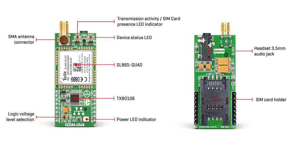
The GL865-QUAD module has to be powered by a clean and stable power supply. The voltage needed for the module to work properly is taken from the 3.3V mikroBUS™ rail and filtered by the filtering network, comprised of several capacitors and a ferrite bed.
Digital sections of the GL865-QUAD are internally supplied by 2.8V, so it is necessary to condition the communication bus lines which connect the host MCU with the module. GL865-QUAD outputs 2.8V from its internal LDO, providing the needed reference voltage for one side of the TXB0106, a 6bit bidirectional level shifting and voltage translator with automatic direction sensing, from Texas Instruments. The reference voltage for the other side of the level shifter is taken from the onboard SMD jumper, labeled as I/O Level This jumper is used to select between 3.3V and 5V from the mikroBUS™, depending on the used MCU type and its logic voltage level requirements.
UART interface supports baud rates from 300 bps to 115.2 kbps and automatic baud rate detection for up to 115.2 kbps. The UART bus of the GL865-QUAD module is connected to one side of the level shifter, while the other side (shifted) is connected to the respective mikroBUS™ UART pins (TX and RX). However, the GL865-QUAD module is designed as the traditional DCE device (Data Communication Equipment) offering the full UART pin count, including the hardware flow control pins (CTS, RTS). These pins are routed to the mikroBUS™ CS (RTS) and the INT pin (CTS) and can be used in the MCU software if hardware flow control is needed.
A yellow LED labeled as STAT, is used to indicate the device status. The device status is indicated by the STAT LED, using the following pattern:
Permanently OFF: The device is unpowered
Cyclically high for 500ms, low for 500ms: Network search / Not registered / Powering off
Cyclically high for 300ms, low for 2.7s: Registered on the network
Always high: Active call
A red LED labeled as the TXD is used at one of the GPIO pins of the module to indicate the SIM card presence. This LED is actually connected to the GPIO 1 pin because the GL865-QUAD does not provide a dedicated SIMIN pin. It might require configuration of the GPIO pins, however, the provided click library offers functions which initialize the module properly, and allow easy communication with the GSM click. Also, the provided application example demonstrates their usage and it can be used as a reference for custom development. To provide enough power for the LEDs, both of them are driven via the NPN BJ transistor.
The PWRMON pin is routed to the mikroBUS™ AN pin, and it is used to provide a 2.8V power good indication. When the module is powered on, the internal LDO will provide 2.8V, biasing the BJT and causing the AN pin to be pulled to a LOW voltage level. When there is no 2.8V, the BJT will be unbiased and the AN pin will be pulled to a HIGH logic level.
The GL865-QUAD offers extensive audio features, including Half rate, full rate, enhanced full rate and adaptive multi-rate voice codecs, superior echo cancellation and noise reduction, multiple pre-programmed audio profiles, fully configurable with the AT commands, and DTMF tone generation. The audio section is integrated into the module and it requires only a few external components. The headset can be connected via the 4-pole 3.5mm audio jack.
As mentioned before, this module features an embedded Phyton Script interpreter. It allows loading scripts written in Phyton language and provides 1.9 MB of non-volatile memory for the user scripts and 1 MB of RAM for the Python engine.
The Micro SIM card holder on the back of the Click board™ is used to install a micro SIM card. This device cannot be used without the valid SIM card, which allows connection to the cellular network. Both 1.8V and 3V SIM card types are supported.
It is recommended to follow a certain procedure when powering down the GSM click. There is a possibility of data corruption if the module is turned off abruptly, while operated. To stop the system before powering it down, the system halt AT command should be issued (AT#SYSHALT).
Specifications
Type 2G GPRS,GSM/LTE Applications GSM click with it’s Telit GL865-QUAD IC is ideal for mobile devices. On-board modules Telit GL865-QUAD GSM/GPRS Radio Region Worldwide Key Features On-board antenna connector as well as 3.5mm quadrupole earphone/microphone jack. SIM card socket integrated at the bottom side of the board. Interface UART Compatibility mikroBUS Click board size L (57.15 x 25.4 mm) Input Voltage 3.3V or 5V
Pinout diagram
This table shows how the pinout on GSM click corresponds to the pinout on the mikroBUS™ socket (the latter shown in the two middle columns).
| Notes | Pin | Pin | Notes | ||||
|---|---|---|---|---|---|---|---|
| Power ON monitor | PWR | 1 | AN | PWM | 16 | GPIO2 | Jammer Detect |
| Reset | RST | 2 | RST | INT | 15 | CTS | UART Clear to send |
| UART Request to send | RTS | 3 | CS | RX | 14 | TXD | UART transmit data |
| NC | 4 | SCK | TX | 13 | RXD | UART receive data | |
| NC | 5 | MISO | SCL | 12 | NC | ||
| NC | 6 | MOSI | SDA | 11 | NC | ||
| Power Supply | +3V3 | 7 | 3.3V | 5V | 10 | +5V | Power Supply |
| Ground | GND | 8 | GND | GND | 9 | GND | Ground |
Onboard settings and indicators
| Label | Name | Default | Description |
|---|---|---|---|
| JP1 | - | Left | Logic level voltage selection: left position 3.3V right position 5V |
| LD1 | PWR | - | Power LED indicator |
| STAT | STAT | - | Device status LED indicator |
| TXD | TXD | - | Transmission activity / SIM Card presence LED indicator |
Software support
We provide a library for GSM click on our Libstock page, as well as a demo application (example), developed using MikroElektronika compilers and mikroSDK. The provided click library is mikroSDK standard compliant. The demo application can run on all the main MikroElektronika development boards.
Library Description
The library carries a generic command parser adopted for AT command based modules. Generic parser.
Key functions:
gsm_cmdSingle - Sends a provided command to the module.
gsm_setHandler - Handler assignation to the provided command.gsm_modulePower - Turns on the module.
Examples Description
The example demo application waits for the cal, and after the call is received the parser will get hang up.
This code snippet shows how a generic parser should be properly initialized. Before the initialization, the module must be turned on, and in addition to this, the hardware flow control should also be turned on.
Commands:
- The first command negotiates the baud rate with the module.
- The second command turns the echo off.
- The third command enables hardware flow control - necessary in case of UART polling.
- The fourth command sets up default message format.
void applicationInit(){// MODULE POWER ON gsm_hfcEnable( true ); gsm_modulePower( true );// MODULE INIT gsm_cmdSingle( "AT" ); gsm_cmdSingle( "ATE0" ); gsm_cmdSingle( "AT+IFC=2,2" ); gsm_cmdSingle( "AT+CMGF=1" );}Along with the demo application, timer initialization functions are provided. Note that the timer is configured according to the default development system and MCUs, changing the system or MCU may require an update of timer init and timer ISR functions.
The full application code, and ready to use projects can be found on our Libstock page.
Additional notes and information
Depending on the development board you are using, you may need USB UART click, USB UART 2 click or RS232 click to connect to your PC, for development systems with no UART to USB interface available on the board. The terminal available in all MikroElektronika compilers, or any other terminal application of your choice, can be used to read the message.
mikroSDK
This Click board™ is supported with mikroSDK - MikroElektronika Software Development Kit. To ensure proper operation of mikroSDK compliant Click board™ demo applications, mikroSDK should be downloaded from the LibStock and installed for the compiler you are using.
For more information about mikroSDK, visit the official page.