


Overview
Click shield for Particle Gen 3 is the perfect way to expand the functionalities of your development board compatible with Particle's B series of cellular IoT modules. It provides two mikroBUS™ sockets to add any functionality from our ever-growing range of Click boards™. We are fully stocked with everything, from sensors and WiFi transceivers to motor control and audio amplifiers.
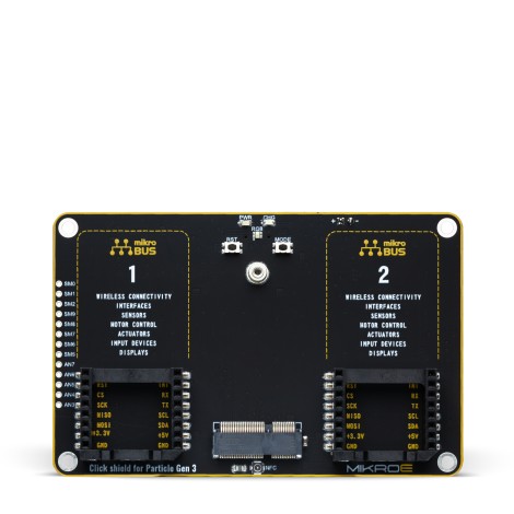
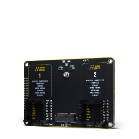
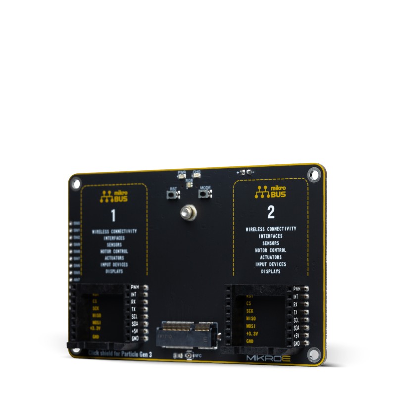
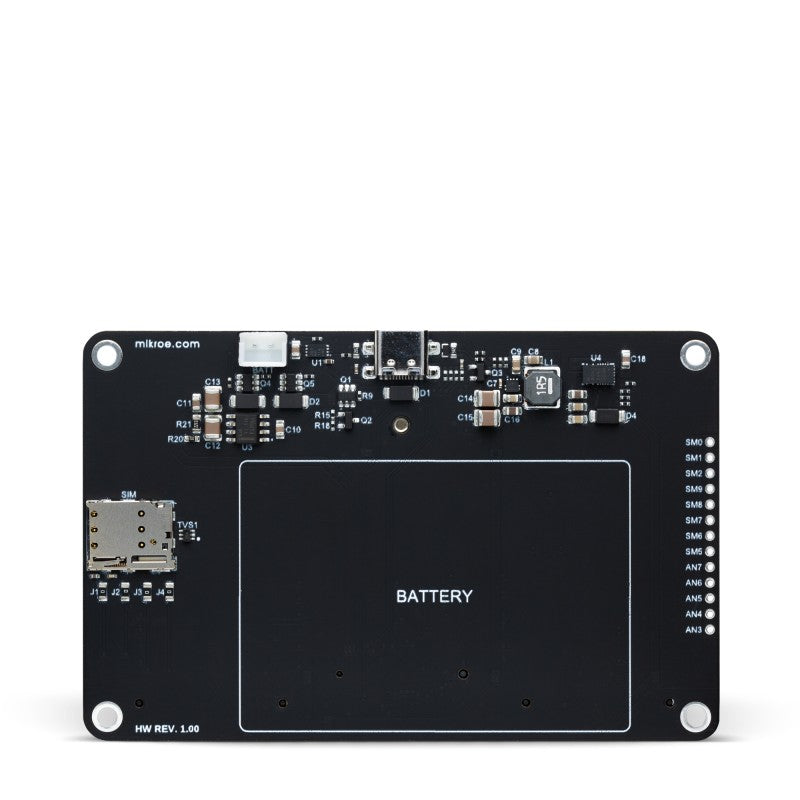
The central part of this Shield’s design includes the M.2 (NGFF) SoM connector, two mikroBUS sockets, a connector for the LiPo battery, NFC antenna, RGB LED, RESET, and MODE buttons, with an additional power supply unit located on the bottom side of the board. It comes with an onboard USB type C connector and a battery connector for backup power supply, including enough power in case you want to switch modules in the future.
This development platform provides users with an effortless and common way to combine the Particle's B series of cellular IoT modules board with their favorite Click boards™ in their upcoming projects.
Note: Particle's B series of cellular IoT modules are not included in the package.
CLICK BOARD
COMBINATIONS
Main features
.jpg)
The Click shield for Particle Gen 3 is designed with an M.2 (NGFF) 67-position connector. It comes equipped with two proprietary mikroBUS™ sockets, allowing the Click board™ devices from our ever-growing range to be interfaced with the Particle's B series of cellular IoT modules with no effort at all. It also includes the M.2 (NGFF) SoM connector,a connectors for the LiPo battery and NFC antenna, RGB LED, RESET, and MODE buttons, with an additional part of the design, the power supply unit located on the bottom side of the board.
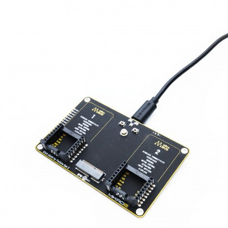
It comes with an onboard USB type C connector and a battery connector for backup power supply, including enough power in case you want to switch modules in the future. Because of that, it can be battery-powered and used as a standalone device. It has the MC34671, a Li-Ion or Li-Polymer battery charger that allows battery charging when Click board™ is inserted in mikroBUS™ socket or plugged into a USB port with the CHG LED indicator indicating the charging in progress.
What is especially respected with the M.2 connector design is that no components are placed underneath the SoM. Since the B series SoMs are two-sided, the RF shielding may hit components under the SIM, preventing the SoM from seating correctly. That’s why the ground plane and traces can and are placed in that zone, while all other components are placed in the opposite direction from this area.
In the addition of the SoM connector, what is still necessary is the hold-down screw to be added on the front side of the board. The M.2 connector does not have integrated locks, so if you don't have the hold-down screw, the module that goes in it will pop right up again. The best option for the screw is to use an M2*3 (M2 2mm screw, 3mm long) with a 4mm head. With the proper standoff and screw, like on this board, the SoM will be level with the board, and the RF shield on the bottom will not touch the baseboard.
On the right side of the top layer of the board, the user can find extra extracted pins (AN and SOM pins) from the M.2 connector that allows easy access to the AN and SoM IO pins. These are “SoM specific pins” which are different for each SoM model. Some of these SOM pins are supporting external SIM on the M.2 interface. The SIM holder is added on the bottom side of the board, allowing an easy SIM change for their future applications. In association with these pins, two of them, SOM3 and SOM4, are connected with a U.FL connector for an optional NFC antenna connection.
On the side of indications and user notifications, RGB status LED is implemented for the simple reason that it is complicated to see what the device is doing without it. The design of the RGB LED includes 1K current limiting resistors, which makes the LED less blinding but still provides sufficient current to light the LEDs. Also, the board has two additional buttons, RESET and MODE, implemented as well, which can be used for hardware reset or change of operating mode.
Once you connect the Particle's B series of cellular IoT modules with our Click shield for Particle Gen 3, it will allow you to access a thousand Click boards™ working with 3.3V or 5V logic voltage level. For checking which Click boards™ is compatible, please open our Click Shop filter. Our Click boards™ are equipped with a library containing functions and example source codes for Mikroe compilers available on LibStock, which can be used, as a reference, for further development.
Power your inventions

When the USB type C connector is connected to the Click shield for Particle Gen 3, the connected Click shield and mikroBUS™ sockets will be powered from it.

When the battery is connected to the battery connector on the bottom side of the board the power will be provided to the Click Shield from it, including mikroBUS™ sockets.

When the USB type C connector and the battery is connected to the Click shield for Particle Gen 3 at the same time, the mikroBUS™ sockets will be powered from the USB Type C connector.
Specification Table
| Type | Shield |
| Applications | Click shield for Particle Gen 3 allows you to combine Click boards™ with Particle's B series of cellular IoT modules. |
| On-board modules | 2x mikroBUS™ connector, 1xM.2 (NGFF) 67-position connector, 1xU.FL connector for an optional NFC antenna, power management unit, SIM card holder, USB type C connector, battery connector. |
| Interface | Analog,GPIO,I2C,PWM,SPI,UART |
| Compatibility | mikroBUS |
| Input Voltage | 3.3V,5V,External |
Gallery


Shipping rates Australia wide and New Zealand
FAQ:
- How do I estimate shipping for my order?
- Add products in the shopping cart and head to the checkout page to estimate the shipping.
Dispatch time
Unless expressly agreed otherwise with you, we will not commence delivery of an order until we have received cleared payment of the purchase price in full.
All orders placed before 11 am AEST (Monday to Friday) will ordinarily be processed on the same day.
We will endeavour to ship the Products by the applicable time indicated on the website, but all times are indicative only. All shipping times are dispatch times only, and actual delivery dates will depend on the shipping method chosen, delivery address and delivery service provider.
Note- Please make a note during purchase if you require any item urgently. However we cannot guarantee that we will be able to comply with any request.
*Go to Australia post delivery time calculation to get various Australia post service in your area please use our shipping postcode Thomastown, 3074 as the "from" address - https://auspost.com.au/parcels-mail/delivery-times.html?ilink=tools-open-deliv-times.
We ship all products throughout mainland Australia, Tasmania and New Zealand - Including Darwin, Melbourne, Sydney, Tasmania, Adelaide, Brisbane, Perth, all metro and regional areas but do not deliver to areas in Australia where the Australia Post delivery network is not available.
Check Express shipping delivery coverage area at - http://auspost.com.au/parcels-mail/delivery-areas.html
Receipt of deliveries
Deliveries to post office boxes are not permitted where delivery is by courier. If delivery is by courier and nobody is available at the delivery address to accept delivery when delivery is attempted then the courier may either:
- leave the relevant parcel at the unattended address (the courier will do so if specified in your delivery requirements); or
- re-attempt delivery at a later time or date, in which case we may charge you an additional re-delivery fee.
Note that if a delivery is left unattended at the shipping address and is subsequently stolen then the theft is your responsibility, not ours.
Payment & Security
Your payment information is processed securely. We do not store credit card details nor have access to your credit card information.